-----------------------------------------------------------------------------------
CARVER TX-11 FILTER PLACEMENT SPECS
The TX-11 has five ceramic filters. F101, 102 and 103 are 180khz filters. F104 and 105 are 250khz filters.
See this diagram for placement:
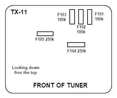
An excellent modification is to remove the two wideband filters (F104 and F105) and replace them with either 150khz or 110khz filters (or one 150 and one 110). Doing this will make your wide setting narrower and your narrow setting truly narrow. The wide setting will still be free enough from any distortion to make music listening enjoyable and the narrow setting will give you that FM station on 96.3 and 100 miles away next to your local on 96.5 15 miles away.
The diagram above can be
accessed by removing the board that sits on
top of it and moving that board to the side while you
do the mod. The upper (smaller) board may have a small wafer capacitor
soldered from it to the RF section, which you will have to unsolder
first.
Four screws with spacers secure the top board. Don't break any green
wires
when you do this.
To add an RDS Decoder to the Carver, find R306 and attach a lead to one side of
the resistor. Only one side will work. Try both to find out which one.
Connect the other lead to GND.
(c)2002 M. Bugaj