Model 3025 - Previously Known as Model 4408
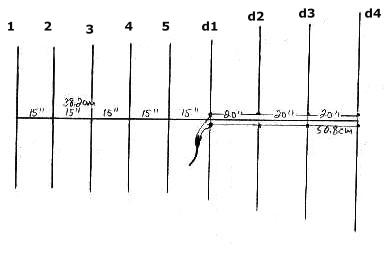
The Channel Master Probe-9 (model 3025) was a workhorse. It was one of the most popular FM antennas in use today by FM Dxers and audiophiles. Gain is good, and front-to-back ratio is good. THIS ANTENNA IS NO LONGER BEING MANUFACTURED. The antenna consists of four folded dipoles (d1 through d4) which are all driven. In front of the dipoles are 5 directors (1-5). Note that there is no reflector as such. The last dipole acts as a reflector. Each dipole is tuned to a specific portion of the FM band. Spacing between each director is 15 inches (38.2cm). Spacing between dipoles is 20 inches, or 50.8cm.
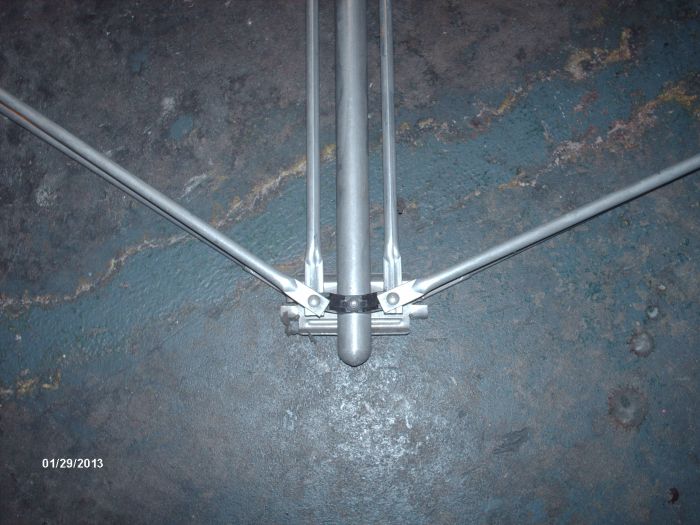
This is the last of the four dipoles. The harness runs from the top of the last dipole to the top of the next dipole.
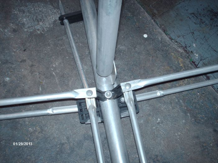
This is the connection from the last dipole to the second dipole. Notice the harness runs under the antenna boom to the third dipole.
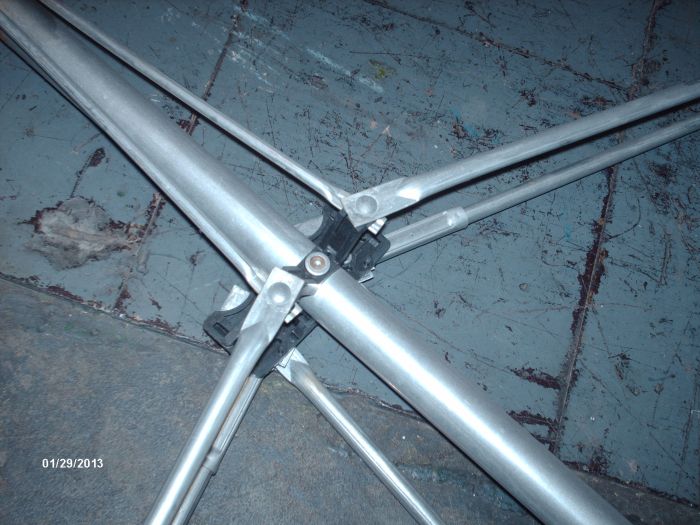
This is the connection to and from the third dipole. The harness runs over the boom to the fourth dipole where the antenna is connected.
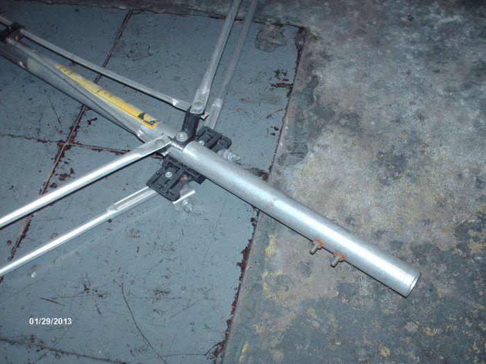
Here we are at the fourth dipole where the antenna is connected and where the two booms are connected. The dipoles have about 2.25" of airspace between upper and lower halves.
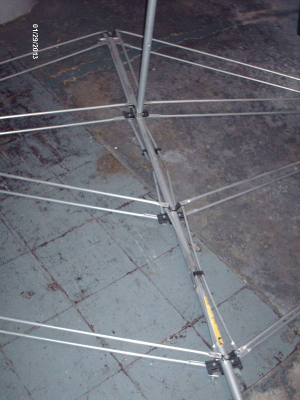
And finally this is the rear half of the Probe 9. The dipoles are not fully extended due to lack of space.
Total Length of All Elements
| Total Length tip-to-tip | |
| Director 1 | 48 inches/ 122cm |
| Director 2 | 49 inches/ 125cm |
| Director 3 | 49 inches |
| Director 4 | 49 inches |
| Director 5 | 50 inches/ 127.5cm |
| Dipole d1 | 54 inches/ 138cm |
| Dipole d2 | 63 infhes/ 160cm |
| Dipole d3 | 68 inches/ 173cm |
| Dipole d4 | 74 inches/ 189cm |
Notice that dipoles d1 and d4 are connected on the bottom of the dipoles, while dipoles d2 and d3 are connected on both the tops and bottoms of the dipoles and that the connections do not cross as on the Finco design.
Total length of the 3025 boom is about 137 inches, allowing an inch or so extra on each end. The connection to your lead/balun is at the bottom of dipole d1.
Please use this information for comparison purposes only.
Additional Information:
Note on dipole connections: To connect the dipoles, Channel Master used the same gauge tubing as their antenna elements (3/8 inch). Connections from d4 to d3 are from the bottom of the dipoles. Connections from d3 to d2 are from the TOP of the dipoles and connections from d2 to d1 are from the bottoms of the dipoles. Dipoles d3 and d2 have both bottom and top connections. All dipoles are completely insulated from the mast and all connections run parallel to each other (they do NOT cross). Directors are NOT insulated from the mast.
© 2012,2013 M. Bugaj No reprinting without permission.